TRON Project is also an “industrial product design” project.
Due to the recent needs of website development, it has been becoming common for computer-related companies to have an in-house design department. Until recently in the computer industry, US Apple was the only company to emphasize design at the same level as technology from the start of the life cycle of a computer development project.
After the success of products by Steve Jobs, we are now in an age where provision of not user interface but user experience including graphics such as logo, interactive operation, and hardware product design as aggregate is regarded as competitive edge of computer manufacturers. In the world of web services, even a great service idea needs to be provided with great design, otherwise, users do not select the service. It is necessary to have an in-house design team to provide a quick service. Outsourcing to a design company after determining product planning and software specification became a thing of the past.
TRON Project has been focusing on artistic design as well as the development of underlying technology, had an in-house design team. The artistic design activity has been directly managed by the project leader based on the concept of “system design = design” from the beginning. This document looks back on the footprints of TRON Project from a viewpoint of artistic design.

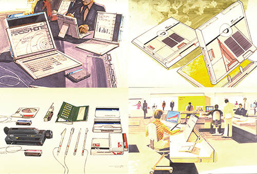
1 Artist’s Rendition of a Future Computer (1982)
A part of the illustration I produced for a 30-minute slide show titled “future office” prepared by Japan Electronic Industry Development Association. There was no laptop PC and digital cameras back then. A network-enabled laptop computer which integrates AV by using semiconductor solid-state memory as standard media can be used as a tablet also. Many engineers saw this concept of computer, and it influenced the product development afterward.
*Japan Electronic Industry Development Association then. Currently Japan Electronics and Information Technology Industries Association.
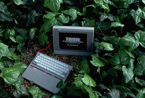
2 Experimental BTRON machine (1985)
The early BTRON PC functional working model. The large open area at the front of the keyboard, used for the electronic pen and doubling as a palm rest, was an original TRON design which has now become the standard for notebook computers.
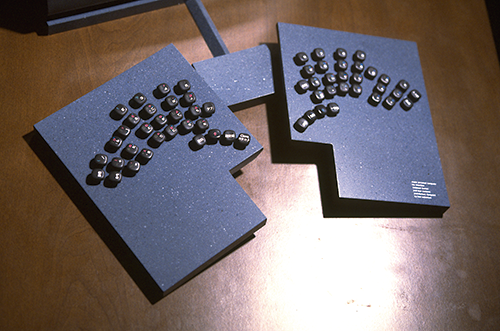
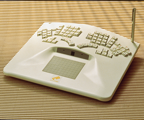
3 Design Study of an Executive Office (1986)
For future computers, I thought much more attention should be given to fashionable design, so I made a design model that could be placed on an executive desk. It has a separate type keyboard, and the keyboard employs slate similar to that used for the black stones in the game of Go.
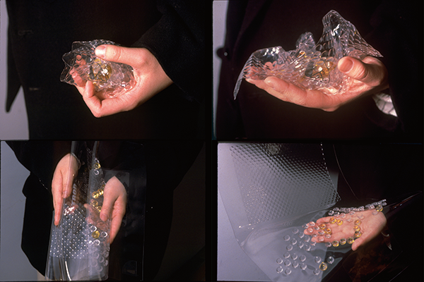
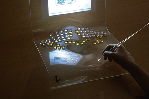
4-5 The Flexible Computer (1988)
A future computer made of a thin, translucent shape memory sheet. The design embodies the view that a communication machine requires no more than display and input; all else is excess baggage.
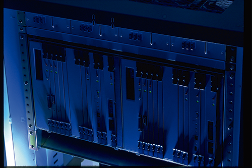
6 CTRON: The OKITRON-L Fault Tolerant Computer with CTRON-specification OS (1994)
CTRON is ultra-multiprocessing real-time OS which was used for ATM switches and other switching systems throughout Japan. The photo shows the high reliability CTRON-specification system which then had been adopted in communication processing systems, network administration, plant control and many other applications.
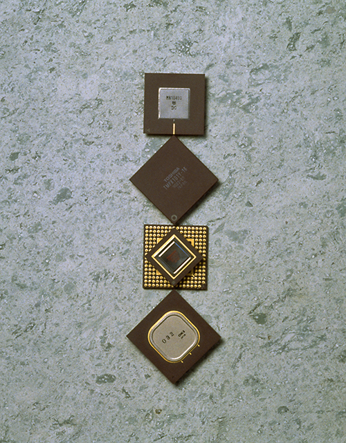
7 TRON chip (1988)
The TRON-specification VLSI CPU project is to develop 32-bit and 64-bit microprocessor specifications. Japan’s first 32-bit microprocessor was made by one of the participating companies, and this project led the development into activities that produced Hitachi SH series, Mitsubishi M series, etc. later.
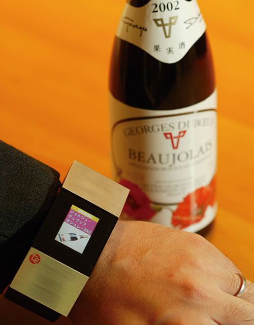
8 Wristwatch type Ubiquitous Communicator (UC) prototype (2004)
This is currently called a wristwatch type wearable device equipped with RFID reader, small color LCD and Wi-Fi. It usually shows the time, and displays related information when it is placed over objects to which an RFID tag is attached and reads ucode. It needed a big battery to provide power to the RFID reader with the technology of that time.
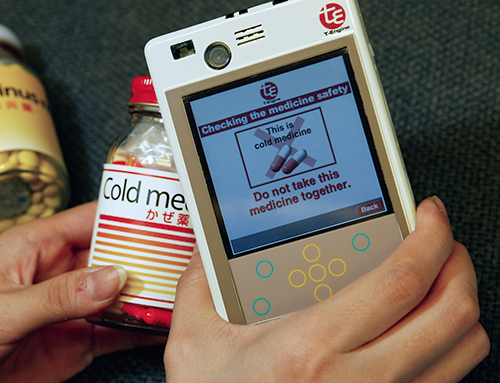
9 Early UC prototype (2003)
With the concept of UC, we aimed to create a “general-purpose communicator” which can communicate with objects as well as people with various types of channels from the beginning. The photo shows the demonstration used for individual drug administration management which warns possible adverse drug interactions by communicating with pill bottles.
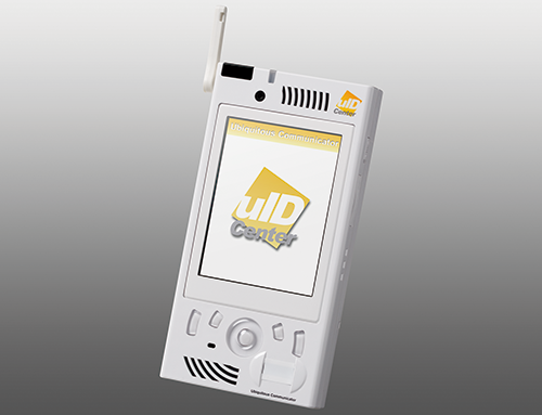
10 UC06 (2005)
A mobile device equipped with Wi-Fi, telephone function, camera function, touch panel display, RFID reader on the back, wireless marker receiver, infrared communication, graphics processor which plays videos, etc. It was slightly big reflecting the technology standard of the day, and had the same functions as current smartphones. It was mass-produced and used in many early feasibility study experiments in various application fields.
11 UC09 (2006)
A downsized UC equipped with a full-sized display and the function same as UC06 thanks to the advent of technology. Feasibility study experiments related to ubiquitous computing which simulate future social environment, foresaw an age where anyone has a device beyond mobile phones, the mainstream of the day―currently called smartphone. There was no product which could be used as is back then, so we developed it ourselves.
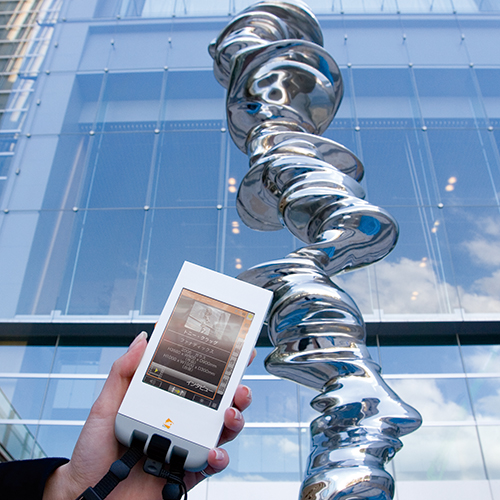
12 Tokyo Midtown / Ubiquitous Art Tour (2007)
Many feasibility study experiments were turned into commercialized and used every day afterward. The tour guide system of the art works in the facility that uses UC has been used in Tokyo Midtown since 2007. Locations are identified by using both wireless markers and infrared markers.
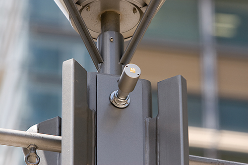
13 Tokyo Midtown / Ubiquitous marker (2007)
Wireless markers were attached to the lamp posts around Tokyo Midtown. The markers send ucode every 0.5 seconds, and this signal can be used to estimate location of UC. Bluetooth LE specification was created and it is commonly used for wireless marker now. There was no such standard in 2007, the system was realized by using specified low power radio (a low power RF allowed by RF regulations in Japan).
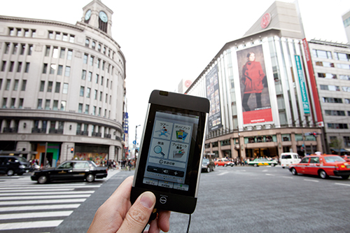
14 Ginza / ucode NFC tag
The nameplates with ucode were attached along with the lamp posts in
Ginza. NFC card has been embedded into the nameplates as passive RFID tag. Information related to them will be displayed by reading the card by using commercially available smartphone.
QR Code is available for the existing mobile phones and iOS devices without NFC.
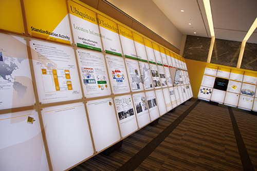
15 Tokyo Ubiquitous Technology Project in Ginza (2007)
Tokyo Ubiquitous Technology Project has conducted full scale experiments of the functions which would be available in future ubiquitous infrastructure by attaching ucode tags and markers in specific areas in a concentrated manner in cooperation with Tokyo Metropolitan Government. In Ginza area, 5,000 tags and markers have been attached, and feasibility study experiments such as support for physically-challenged people, guide for foreign tourists and shopping support have been conducted continuously.
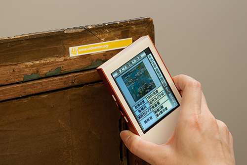
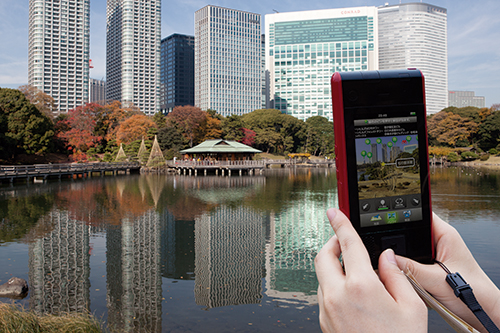
16 Hama-rikyū / Gardens Information Service (2010)
A guide system that uses ubiquitous infrastructure has been used commercially at Hama-rikyū. It has been well received by foreign tourists and always been fully booked. It is more fun to visit Japanese gardens if you have the knowledge on their histories and background. Signage may spoil a view and cannot have explanations in multiple languages due to the small display area space, so the guide system that fits in your hand is more preferred.
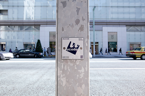
17 ucode tag for Public Facility Management (2012)
ucode tag has been used for public facility management in certain areas such as the surrounding area of the Tokyo Metropolitan Government Building in Shinjuku. Electronic tags may not need to stand out as it can be read via radio waves. However, it should be noticeable to be used by more interested people, so the square ucode mark shown in the photo is effective.
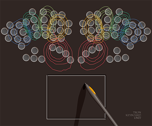
18 TRON Keyboard Unit (1986)
The key shape and layout were designed based on an analysis of finger movement to type 1.6 million characters of text to determine key use frequency for kana-kanji conversion. The study included the surveys of the size and motion of fingers and arms of 150 subjects ranging between 20 and 60 years in age.
19 TRON keyboard TK-1 (1991)
The TRON-specification keyboard TK-1 was developed and provided by Personal Media Corporation as a commercial product. It connects directly to the MCUBE, a pure-TRON machine (it had TRON LSICP and ITRON specification OS), or via an adaptor to DOS/V PCs where it can be used with the B-right/V OS. The electronic pen adopts a wireless design that does not require batteries.
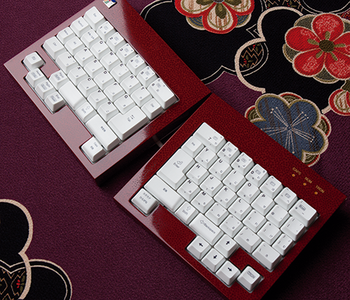
20 Tsugarunuri lacquering µTRON keyboard (2008)
Basic TRON keyboard is ergonomically ideal, but it is big. So, I designed the µ version which can be packed compactly and be separated and put as you like to fit your position. This is the Tsugarunuri lacquering version.
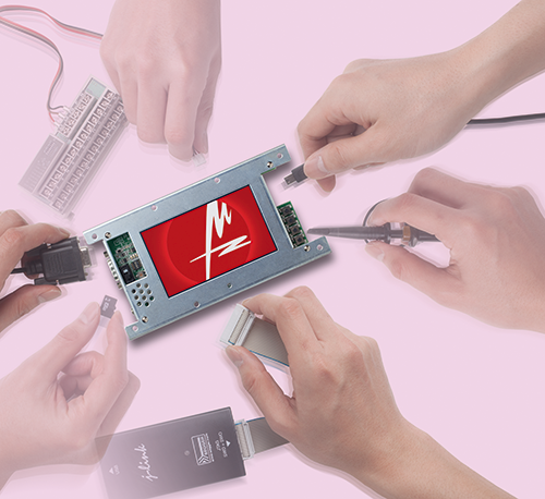
21 µTeaboard 2.0 (2013)
A learning kit was on sale for disseminating embedded system development education that used T-Kernel. It is equipped with a touch-screen display and rich interface, and can be used as a microcomputer board to control manufacturing facilities for plants which are barely manufactured, etc.
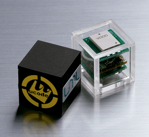
22 UWB dice (2007)
A super low-power active RFID tag that uses Ultra Wide Band (UWB). If it sends ucode every five minutes only, it can operate for nine years. It is called dice as the overall profile equipped with antenna, circuit board and small coin cell battery fits in a 10-millimeter square cubic case, and looks similar to a dice.
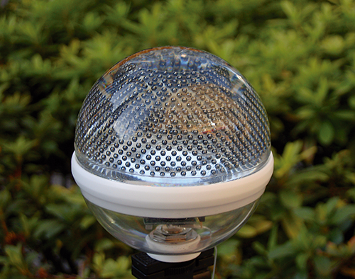
23 pT-Engine solar sensor ball (2005)
A prototype of solar sensor network node which wirelessly sends the data of temperature, humidity, carbon dioxide level, etc. The same aperture efficiency can be obtained as optical incidence from the whole sky at any time of the daytime by embedding spherical solar cell array into acrylic hemisphere. It was assumed to put many sensor poles that have the spherical object with about 10 centimeters in diameter at their tips in farmland.
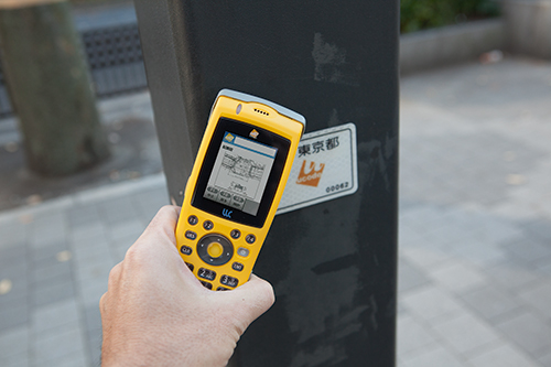
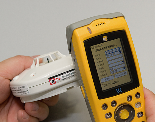
24 Fire Alarm Traceability / UC for business use (2007)
This yellow UC is impact-resistant, waterproof, dust-resistant and button operable, which is specified for construction crews who need to operate this device wearing gloves. It is equipped with an RFID reader and camera system bar code reader. It is mass-produced and has been used commercially for traceability at a construction site.
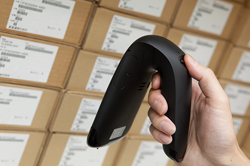
25 UHF/HF Multi-protocol Reader/writer (2012)
Passive RFID has various physical standards, and there is no versatile RFID. So, we developed multi-protocol reader/writer which can support various standards. The reading result is supposed to be sent to smartphone. It is designed by modeling after plasterer’s trowel so that it can scan for quick inspection even when it is held in a variety of ways.
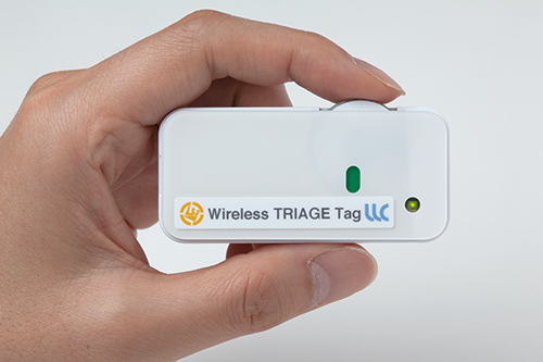
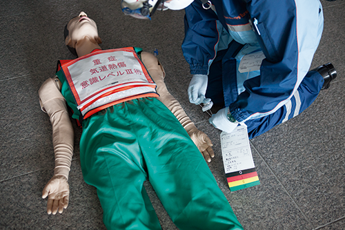
26-27 Wireless Triage Tag (2014)
It is important to determine the priority of the patients’ treatment quickly at a large-scale disaster sites. With the current paper triage tag, counting is performed manually and ever-changing on-site circumstances cannot be reflected. By using wireless triage tag, level changes are counted automatically and wirelessly, and are sent to the network, so resources can be allocated properly at the headquarters.
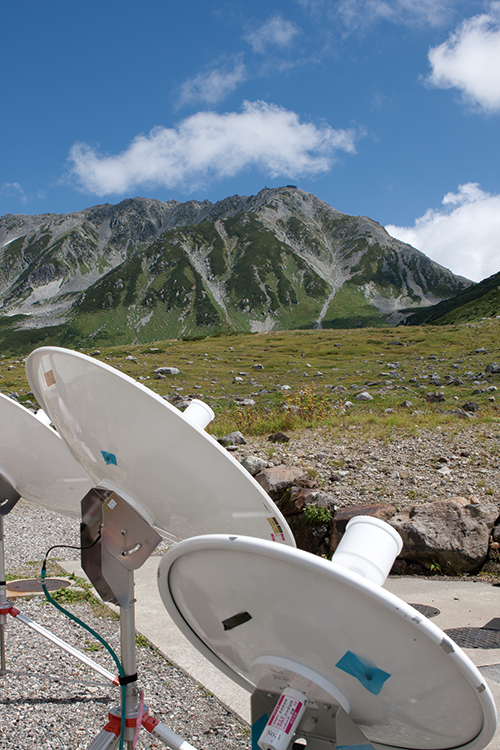
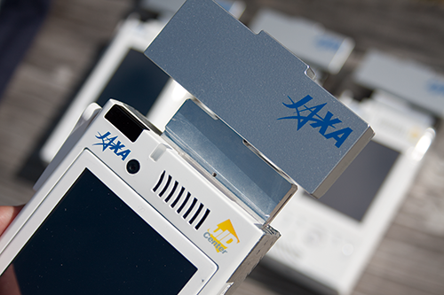
28-29 Mountain rescue drill that uses UC (2008)
The Engineering Test Satellite-VIII “KIKUNo.8” (ETS-III) with a huge antenna as large as two tennis courts can communicate with a small antenna on the earth. UC can directly communicate with the satellite communication, so we conducted an experiment of mountain rescue that uses such satellite communication. It was low power and could show its merit in times of disaster, but the plan was halted unfortunately due to the budget review and project screening by the Japanese government.
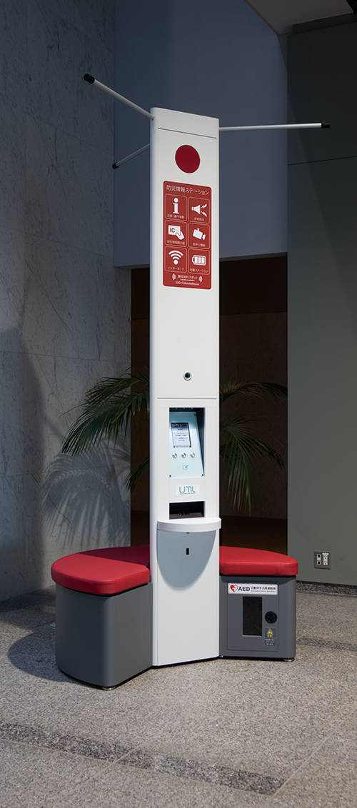
30 Disaster-relief Information Kiosk (2014)
Mobile phone network is vulnerable at the time of a big disaster that affects very wide area. However, SNS, etc. are more useful than telephone call if communication lines for SNS are available. Therefore, we developed a station which provides Wi-Fi service in ordinary times, recharges people’s phones and offers minimum packet communication by using rechargeable battery in times of disasters. We proposed the Japanese government to replace pay phones with such Kiosks.
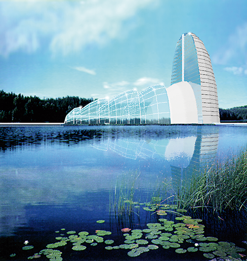
31 TRON Computer City (1989)
Targeting an actual 600,000 tsubo (1,983,471 square meters) site in Chiba prefecture, there was a plan for a next-generation city. The design motif is a combination of geometrically simple tertiary curved objects. Such a design is much more at home in natural surroundings, but it is more difficult to design and build than simple box-shaped structure and needs an advanced computer. This illustration shows the design of office/commercial facility building integrated with a concert hall.
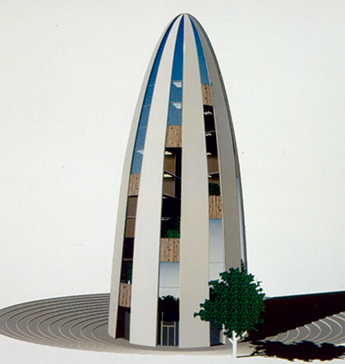
32 TRON Intelligent Building (1989)
A project of the research group of 11 private sector companies which studied how future office building that uses computer technology should be. Unfortunately, we only conducted an experiment and did not create an actual building. We were surprised to know that buildings very similar to this one were built in London and Barcelona later in the news.
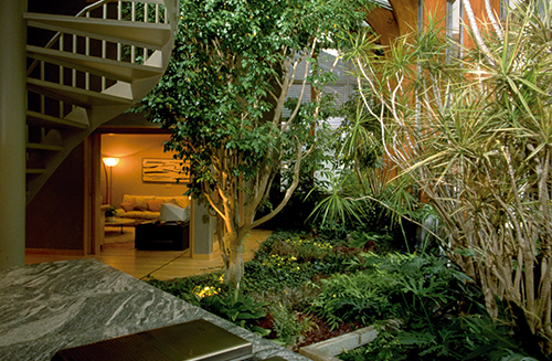
33 Intelligent House Semi-open Space (1988))
An indoor space similar to an ordinary household garden enclosed by glass walls and roof. The glass enclosure opens and closes by computer control based on weather conditions outdoors. The essence of the design is “dynamic form.” The automatic operations controlled by computers were designed to bring about unobtrusive changes in gentle gradations, so as not to be more noticeable.
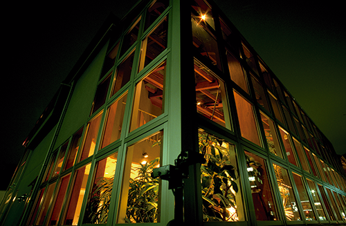
34 Intelligent House Night View of Semi-open Space (1988)
If a house is to be designed from the ground up as a computerized house, for that very reason care should be taken to keep the computerization out of sight. We adopted a simple two-story squarish exterior shape, and used natural materials throughout. In the corner are warning sensors, for detecting intruders anywhere around the outside of the house.
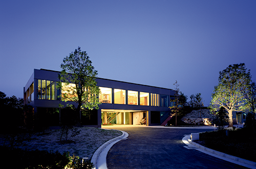
35 Night View of the Exterior / PAPI (2004)
An experimental house built on the premises of TOYOTA CENTRAL R&D LABS., INC. on the occasion of Expo 2005 Aichi Japan. It is a box-shaped building that utilizes ramen unit construction, the specialty of TOYOTA HOME. As it was built in a simple manner and uses photocatalytic coating, the external walls were maintenance-free. It is easy to downsize the home, and the outer walls made out of glass and aluminum are all recyclable.
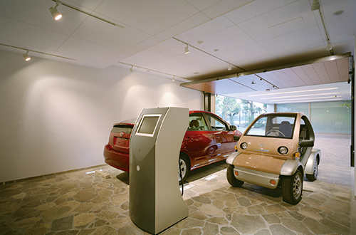
36 Garage/PAPI (2004)
There is serious concern about power shortage in times of disaster. The first experiment of the idea that power can be provided to household by using the engine of PRIUS in case of power outage was conducted at PAPI. The recharger stand for small electric shopping cart (next to it, in the photo) serves as the power supply stand to the house in case of blackout.
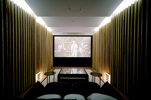
37 Home Theater / PAPI (2004)
The home theater was transported from the factory and set up on site after it was decorated in the factory as a unit of a completed home theater by utilizing the features of ramen unit construction, and the audio equipment was tuned to a particular house. We made the sound field effector in cooperation with YAMAHA.
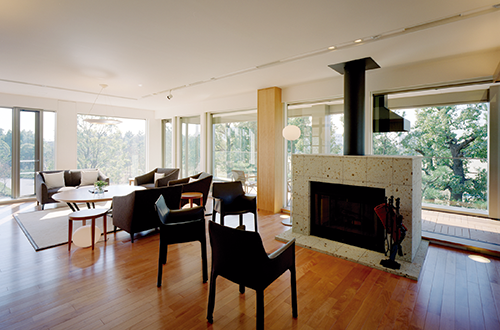
38 Living Room / PAPI (2004)
The exterior of PAPI is simple and function-oriented. The interior prioritizes the lifestyle by using natural material. The fireplace made of Izuishi stone symbolizes the house. A high function wall unit that has blind and air space for heat release between the two sets of double-glazed glass is used around the fireplace.
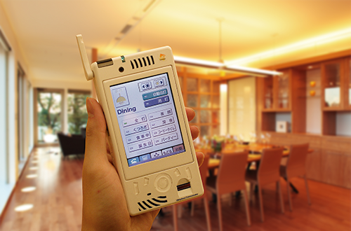
39 UC / PAPI (2004)
There was no smartphone back then. UC was developed from scratch (device itself) for the concept that all family members shall always have devices that serve as all-purpose remote control. UC recognizes the location in the house, and the list of operable control items in the current location is automatically shown on the home screen.
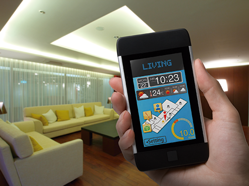
40 UC / u-home (2010)
u-home was designed for the showroom of a future house in Taiwan. It emphasizes that most of the ideas I have been developing for future houses can be provided at a practical and reasonable cost.
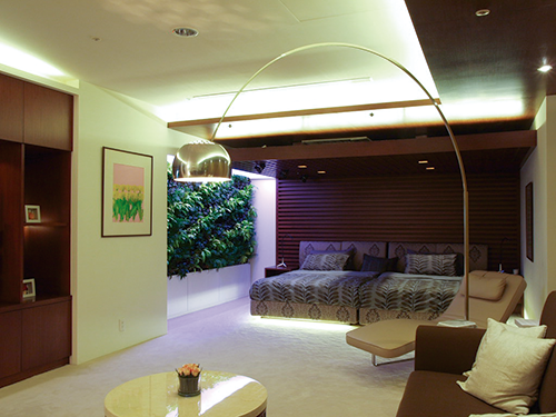
41 Master Bedroom / u-home (2010)
Unlike the previous Intelligent House series, u-home would be a house in a housing complex. So, I wanted to use greeneries for its interior as much as possible, and put up the walls that cultivate foliage plants hydroponically in a vertical plane in many places.
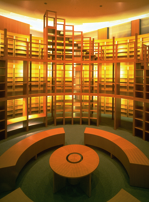
42 Library (1998)
Large cylindrical bookcases are designed to adjoin the entrance hall in the head office of a company. Cylindrical shapes are a common motif in this building. Each bookcase is equipped with an LED matrix display using characters and symbols to help users find the location of books.
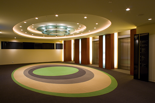
43 Elevator Hall / Tokyo Midtown Conference (2007)
We built a ubiquitous guidance system in Tokyo Midtown. Aside from this, I designed the interiors of the conference floor. Rental conference rooms usually have functional but characterless interior, so I wanted to surprise users in a pleasant manner at the moment the elevator doors open.
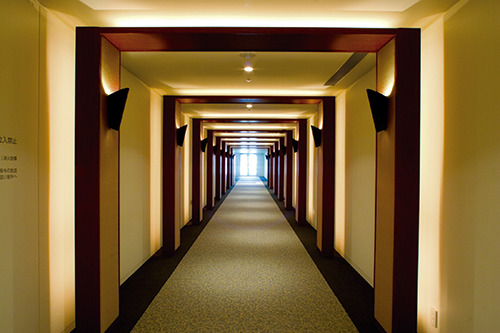
44 Hallway / Tokyo Midtown Conference (2007)
The hallway used in the TV CM of Mitsui Fudosan Co., Ltd. A simply long straight hallway was built due to the internal layout. I added texture in the image of a torii, the gate of Inari Shinto shrine. In the conference room complex with which both the hosts and visitors are not familiar, I intend to make them aware of the location by showing different images every time they turn the corners.
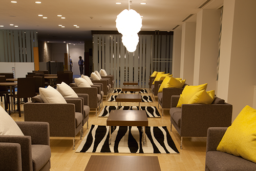
45 1F Lobby / The Head Office Building of SATO CORPORATION (2010)
In order to realize the concept of establishing a cafe & bar space for after-work communication on the first floor, I designed the interiors that can be used both for business setting and after-work communication by controlling ambient lighting by the exterior light and indoor lighting.
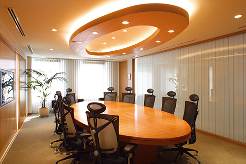
46 The Board Room of a company (2002)
The ceiling lighting and table are both created in the motif of ellipse. The power source and LAN socket are placed in the drawer for each seat under the table. These are often placed on the table, but the lid of the socket holes looks ugly. When the cables come out of it, it looks a mess. The lid needs to be protected from spilled water, even. To solve these problems, I placed them under the table.
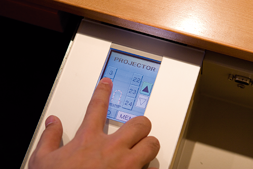
47 Touch Screen / Board Room (2002)
The touch screen type control unit placed in the drawers of the socket at each seat. It controls the equipment in the conference room such as a projector and blind. It shows different sets of controllable items by working with the RFID reader placed under the tabletop and recognizing the employees’ identification cards.
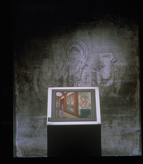
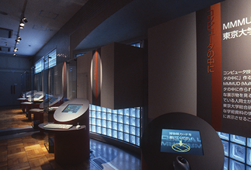
48 MUD (Multi-User Dungeon) / Digital Museum (1997)
The computer creates virtual spaces where museum visitors can enter and move around freely. Two or more people in the same virtual space can even converse with each other, and the docent can explain the displayed items. This example shows a replica of the main hall of the Hōryūji Buddhist temple, which was destroyed by fire.
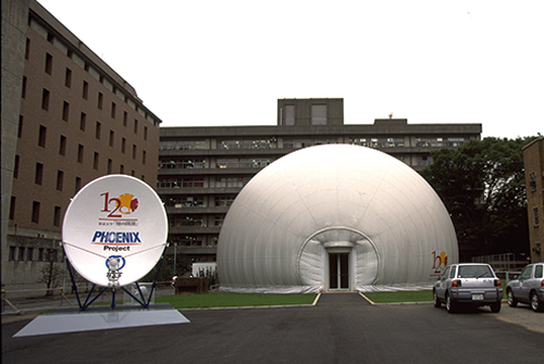
49 Open Academia (A Special Exhibition to celebrate the 120th Anniversary of the University of Tokyo —— The Past, Present and Future of Learning)(1997)
As part of the event to commemorate the 120th anniversary of the University of Tokyo, a special pavilion with a TV studio was set up. The concept presented here was that universities are going to have to take a more active role in providing information. Via satellite broadcasting and video streaming that was conducted experimentally then, the university was on public display for two months, day and night, including classroom lectures, research activities and student life.
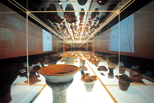
50 Digital Museum 2000 (2000)
A special exhibition was held at The University Museum, the University of Tokyo for proposing the concept of the Digital Museum. To show how to store the material in digital form and propose a new presentation method, the Jomon potteries owned by the University of Tokyo were exhibited in a manner similar to displaying jewelries at a jewelry shop.
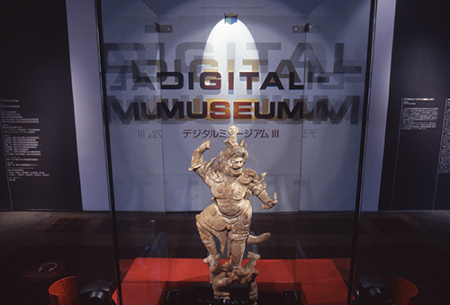
51 Digital Museum III (2002)
Digital Museum 2000 was the Special Exhibition Part 2 with the same concept as the previous one. Those involved in museums were highly interested in the exhibition, and the digital technologies for exhibition were being developed one after another back then, so the third special exhibition which focused on the presentation methods was held.
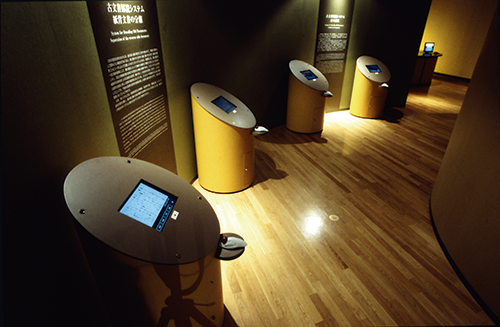
52 Digital Museum III (2002)
The concept of exhibitions based on the mobile devices that use browser and Kiosk terminals is common now. But it was presented here first. Due to cost constraints, the chassis was made by using the thick void tubes for construction (paper tube) to set up many Kiosk terminals inexpensively.
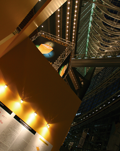
53 TRONSHOW2005
For each annual TRONSHOW exhibition, we select a main motif, and develop a design based on it. As uID was the main feature in TRONSHOW2005 (in 2004), yellow cube was selected as the key motif of the design to utilize the huge space at Tokyo International Forum, the venue of that year’s TRONSHOW.
54 TRONSHOW2008
In TRON Project, the red circle stands for T-Engine, and the yellow square stands for uID. So, a red circle balloon and yellow square balloon were in the open ceiling space of Tokyo International Forum in 2007.
55 TRONSHOW2009
After I had designed several things for Tokyo Midtown, we started holding the annual TRONSHOW at the hall in the first basement of newly built Tokyo Midtown.
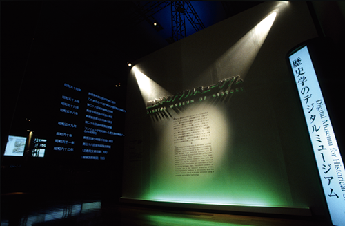
56-57 Digital Museum of History (2001)
For the Special Exhibition Part 3 held in Tokyo National Museum, we designed a new museum presentation where explanation that used RFID, etc. according to the interests of the viewers is provided. This presentation was meant to make the best use of the historical information database which has been accumulated by the Historiographical Institute, the University of Tokyo.
58 ET2006
There was a big change in the first half of 2000 in the long history of my designing exhibitions related to TRON Project. The decoration method of the venue was changed from the construction work using plywood by carpenters to the assembly of standard module as if it responded to the changes of the computer software development. Now I needed to express the identity by using modules.
59 ESEC2008
As TRON Project is an open project supported by donation, public promotion is also a very important activity for us. TRON Project has exhibited mainly at real-time system computer exhibitions in home and abroad actively, and we have also done the booth design ourselves. The logo of the red circle to stand for T-Engine really stands out anywhere.